Arafruit 32U4 breakout board+でArduino Leonardoのファームウエアを試すTrying Arduino Leonardo with Arafruit 32U4 breakout board+
1.はじめに
先週NYCで開催されたOpen Hardware Summitで新しいArduinoが発表されました。
その中でローエンドと位置づけられるArduino Leonardは、USBを内蔵したマイクロプロセッサであるATMega32U4を採用しています。まだ回路は公開させていませんが、USB周りは利用するピンが決まっていますので誰が設計しても変わりません。あとはピンの配置だけで、素直な作りが想定されます。
Arduino Leonardoの発売はまだ10月ですが、すでに公開されているArduino 1.0 RC1には、そのソフトウエアが含まれています。そこで、一足先にAdafruitの開発しているArafruit 32U4 breakout board+を使って、Leonardoの使い勝手を試してみました。
1.Introduction
Last week a set of new Arduino is introduced at Open Hardware Summit.
I’m interested in Arduino Leonardo, which is the low end board with ATMega32U4 micro processor with USB. Although the schematic of Leonardo is not published at this point, the design of Leonrdo must be straight forward, except the assignment of digital and analog pins.
The firmware and core codes for Arduino Leonardo are already in Arduino 1.0 RC1, which was published in September 17.
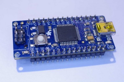
I decide to try Leonardo with Arafruit 32U4 breakout board+, as it also uses ATmega32U4.

2.Requrements
- Software : Arduino 1.0 RC1, you can download here
- Hardware : Arafruit 32U4 breakout board+ , you might use any 32U4 board
- Tools : ISP programmer such as ,USBTinyISP, and AVRISP by ATMEL
- LED, Pods and registers
3. Burning the boot loader
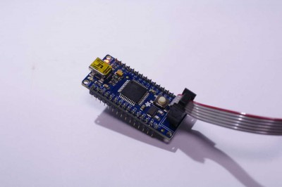
You need to burn boot loader from Arduino 1.0 RC1. I use ISP programmer with the following steps.
- solder an ISP connector on 32U4 Breakout board. Connect ISP programmer with the connector.
- On Arduino 1.0 RC1, choose ‘Tools’ ->’ Board’ -> ‘Arduino Leonardo’
- Choose ‘Tools’ -> ‘Programmer’ -> ‘USBTinyISP’
- Choose ‘Tools’ ->’BurnBootloader’, then wait a couple of minutes
4. Try Blink example
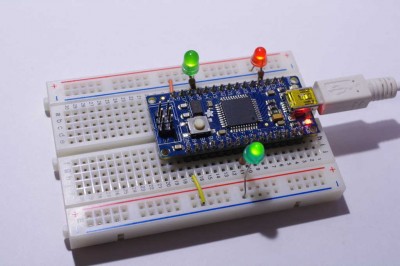
- After burning firmware, I connected the breakout board to Mac with USB port. From Mac, the board is recognized as ‘Arduino Leonardo’
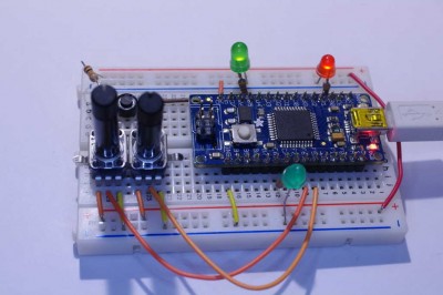
- Connect two 10K Ohm pods to A1(PF6) and A2(PF5).
- Connect a tact switch to D6(PD7) and GND
- Connect a LED and register to D5(PC6)
- ソフトウエア:Arduino 1.0 RC1 リンクはこちら
- ハードウエア:Arafruit 32U4 breakout board+ (実は32U4を使ったボードならほとんどオーケーかも)
- ツール:ISPプログラマ (USBTinyISPを利用しましたが、ATMEL純正のAVRISPなども利用可能)
- その他、LEDなど必要なハードウエア
- 32U4にISPコネクタをハンダづけ。ライタに接続
- Tools -> Board -> Arduino Leonardoを選択
- Tools -> Programmer -> USBTinyISPを選択
- Tools ->BurnBootloaderを選択
- A1(PF6), A2(PF5)にボリュームを接続
- D6(PD7)にタクトスイッチを接続
- D5(PC6)に電流制限抵抗とLEDを接続
I open an example sketch named blink, then download the program to Leonardo.
5.Human Interface Device (Mouse)
The most interesting feature of Arduino Leonardo is the emulation of Mouse and Keyboard. One can make USB-HID class device with Leonardo.
I tried one of example sketch named JoystickMouseControl for the next step.
The following hardware setting is used for my trial.
The following pins are assigned on Arduino Leonardo, according to the file (hardware/arduino/variants/leonardo/pins_arduino.h)
// ATMEL ATMEGA32U4 / ARDUINO LEONARDO
//
// D0                 PD2                    RXD1/INT2
// D1                 PD3                    TXD1/INT3
// D2                 PD1        SDA         SDA/INT1
// D3#                PD0        PWM8/SCL    OC0B/SCL/INT0
// D4        A6       PD4        ADC8
// D5#                PC6        ???         OC3A/#OC4A
// D6#       A7       PD7       FastPWM      #OC4D/ADC10
// D7                 PE6                    INT6/AIN0
//
// D8                 PB4                    ADC11/PCINT4
// D9#       A8       PB5       PWM16        OC1A/#OC4B/ADC13/PCINT5
// D10#      A9       PB6       PWM16        OC1B/0c4B/ADC12/PCINT6
// D11#               PB7       PWM8/16      0C0A/OC1C/#RTS/PCINT7
// D12       A10      PD6                    T1/#OC4D/ADC9
// D13#               PC7       PWM10        CLK0/OC4A
//
//           A0        PF7                    ADC7
//           A1        PF6                    ADC6
//           A2        PF5                    ADC5
//           A3        PF4                    ADC4
//           A4        PF1                    ADC1
//           A5        PF0                    ADC0
//
// New pins D14..D17 to map SPI port to digitial pins
//
// D14                 PB0                    RXLED,SS/PCINT0
// D15                 PB1                    SCK,PCINT1
// D16                 PB2                    MOSI,PCINT2
// D17                 PB3                    MISO,PCINT3
//
// TXLED               PD5
// RXLED               PB0
// HWB                 PE2                    HWB
EOF
2.準備
3. ブートローダの書き込み
Arduino 1.0 RC1からISP経由でブートローダを書き込みます。書き込みは以下の手順になります。
4. Blinkを試す
ファームウエアを書き込んだ32U4ボードをUSBにつなぐと、PCからはArduino Leonardoと認識されます。
あとは普通にIDEからスケッチの書き込みが出来ます。
ExamplesにあるBlinkを書き込んでみました。
実際のブリンクの確認にはD13(PC7)にLED+電流制限抵抗を接続することが必要です。また、上の写真は確認のためTxD, RxDにもLEDを接続しています。
5.Human Interface Device (マウス)を試す
Arduino Leonardoの最大の特徴は、マウスやキーボードなどのUSBデバイスを作成できることにあります。
そこで、ExamplesにあるJoystickMouseControlを試してみました。
必要なハードウエアの設定は次の通りです。
6.ピン配置について
ソースコード(hardware/arduino/variants/leonardo/pins_arduino.h)によると、ピン配置は次のようになっています。
// ATMEL ATMEGA32U4 / ARDUINO LEONARDO
//
// D0                 PD2                    RXD1/INT2
// D1                 PD3                    TXD1/INT3
// D2                 PD1        SDA         SDA/INT1
// D3#                PD0        PWM8/SCL    OC0B/SCL/INT0
// D4        A6       PD4        ADC8
// D5#                PC6        ???         OC3A/#OC4A
// D6#       A7       PD7       FastPWM      #OC4D/ADC10
// D7                 PE6                    INT6/AIN0
//
// D8                 PB4                    ADC11/PCINT4
// D9#       A8       PB5       PWM16        OC1A/#OC4B/ADC13/PCINT5
// D10#      A9       PB6       PWM16        OC1B/0c4B/ADC12/PCINT6
// D11#               PB7       PWM8/16      0C0A/OC1C/#RTS/PCINT7
// D12       A10      PD6                    T1/#OC4D/ADC9
// D13#               PC7       PWM10        CLK0/OC4A
//
//           A0        PF7                    ADC7
//           A1        PF6                    ADC6
//           A2        PF5                    ADC5
//           A3        PF4                    ADC4
//           A4        PF1                    ADC1
//           A5        PF0                    ADC0
//
// New pins D14..D17 to map SPI port to digitial pins
//
// D14                 PB0                    RXLED,SS/PCINT0
// D15                 PB1                    SCK,PCINT1
// D16                 PB2                    MOSI,PCINT2
// D17                 PB3                    MISO,PCINT3
//
// TXLED               PD5
// RXLED               PB0
// HWB                 PE2                    HWB
EOF


Thanks for documenting your findings! I’d like to make my own tiny Leonardo variant and I was having a little trouble finding pin mappings considering the schematic wasn’t published yet. Take care!
How can I use Arduino Duemilanove or USBasp programmer instead of USBtinyISP to burn the boot-loader of Arduino Leonardo on to ATmega32U4 chip? Thanks
“アルドゥイーノDuemilanove”または代わりにUSBtinyISPのUSBaspのプログラマを使用するには?ATmega32U4チップへのArduinoのレオナルドのブートローダーを書き込むためにそれを使用するには?
感謝
Find a configuration file located at “hardware/arduino/programmers.txt” in arduino IDE.
Add an entry for Usbasp described below;
—-
usbasp.name=Usbasp
usbasp.protocol=usbasp
—-
Now, you can choose Usbasp in Arduino IDE.
-Yoshi
Thanks for that awesome posting. Useful, and it saved MUCH time! 🙂
Thanks for USBasp tips.
I have made my own ATmega32U4 board and downloaded Arduino L30N4RD0 bootable to it.
When I connect the board to PC, it request driver/software for Arduino L30N4RD0 bootable!
Where can I find the it?
私は自分のATmega32U4ボードを行っています。とそれへのブート可能なArduinoのL30N4RD0をダウンロード。
私はボードをPCに接続すると、それはドライバ/ブート可能なArduinoのL30N4RD0のソフトウェアを要求する!
それはどこで見つけることができますか?
[IMG]http://i53.tinypic.com/10nam3b.jpg[/IMG]
http://tinypic.com/r/10nam3b/7
Although I didn’t try myself, the driver for Windows seems to be in Arduino 1.0 RC1 package. Find the file named “Arduino Leonardo.inf” in drivers folder.
-Yoshi
Thanks a lot!
Yoshi あなたは天才です!
The custom made ATmega32U4 board is detected as Arduino L30N4RD0!
But when I try to upload the program: It uploads only about 90% and doesn’t reach 100%.
Why? (HWB pin set to ground via 100 Ohm resistor)
Also if I connect USBasp I can program the board through it but I want to program directly through Arduino L30N4RD0.
ここでの写真です
http://i54.tinypic.com/257d89d.jpg
After it stuck there for a minute, Ihave pressed RESET and ここでの写真です
http://i56.tinypic.com/2v809ab.jpg
got this error:
avrdude: ser_send(): write error: sorry no info avail ??
こんにちはヨッシー
私は問題を修正しました。それは、HWBに関係しています。それは滑らかなwithArduino L30N4RD0のソフトウェアを動作します!
ご協力いただきありがとうございます。
Bhags-san
I’m grad to hear you had succeeded. Enjoy your new toy. -Yoshi
Thanks 🙂
Do you know if Arduino Leonardo supports USB serial?
For example Teensy supports upto 12Mbits/sec
http://www.pjrc.com/teensy/td_serial.html
I’ve tried with Leonardo and I’m getting only 690Kbits/sec! Too slow.. :-((
@Bhags
I have the same problem, what is the solution?. I don’ t understand about HWB.