7segduino

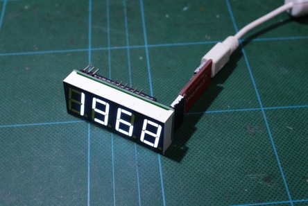
I Introduce new Arduino-clone named “7segduino”. I designed an Arduino-clone board which just fit under a 7segment-4digit LED module. Arduino IDE and programming environment are applicable for the development of application.
-
1.Circuit Design
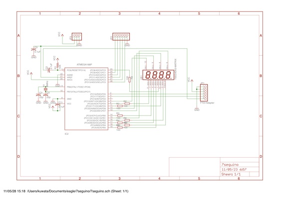
The circuit is minimum parts for Arduino. The following describes main components of 7segduino.
(A) LED Driver
The LED module is directly connected to AVR I/O pins with register, and no external LED Driver is used. By this design, I can reduce the number of parts used for 7segduino. Pins are assigned according to the physical pin assignment of LED module to minimize the path.
(B) Clock Circuit
In general use, RC oscillator is recommended to minimize the number of parts. A crystal and two capacitors in the diagram should not be installed.
Just for the cases where accurate timing is require, such as clock and frequency measurement, 16MHz crystal is recommended.
Please note that boot loader and setting for fuse bit are different for each cases.
(C) Tools for Programming
The following tools are required for setting AVR and writing application program.
- AVR writer
You need AVR writer, such as TinyISP, is required to write boot loader.
- USB-Serial bridge ex. FTDI adapter
FTDI adapter is used to program 7segduino
-
2.Parts
(A) 7 segment 4 digit LED matrix module, anode common
(B) ATMega328P and 28PIN DIP Socket
(C) Chip register, 100 ohm x 8, 10k ohm x 1, size = 1608
you need to adjust 100 ohm to fit voltage you use and spec. of LED.
(D) Chip Capacitor (100nF x 3)
(E) Pin Header ( 6 x 1, 6 x 1 , 3 x 1 )
(F) 7segduino PCB
-
3.How to assemble
-
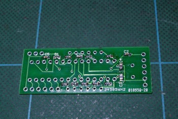
(1)solder all chip resister and capacitor in the front side of PCB. It is very important to check the connection of chips, as we cannot touch this side once LED is installed.
all of SMD parts are soldered in the front side
-
(2)Solder 28PIN DIP socket and pin header in the back side of PCB
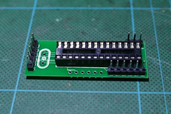
socket and pin header is soldered in the back side.
-
(3)At this point, you need to prepare AVR chip programmed. You can use Arduino and AVR programmer to write bootloader. After the program is done, AVR should install on the 28PIN DIP socket of 7segduino PCB. It is recommended to check if bootloader works with Arduino IDE. For the test, you need to connect USB-Serial cable to the pin header of 7segduino and connect USB to host PC.
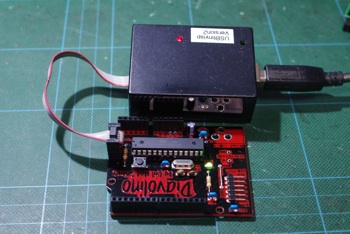
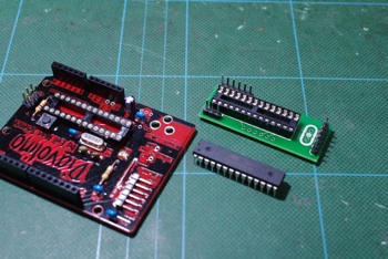
write bootloader to AVR and move the AVR to 7segduino PCB
-
(4)Cut all of extra lead in the front side of PCB. It is recommended to make front side of PCB as flat as possible. Solder LED module in the front side of PCB. Please check direction of LCD module. FTDI connector should be RIGHT side when you face LED module.
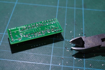
In oder to avoid LED make front side flat !
-
(5)You can write your sketch from Arduino IDE. I recommend to try hello_7seg.pde for the first run.
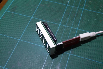
Completed!
-
4.How to use
A library for 7segduino, named “Sseg Library” is prepared.
Several examples are included in the library.
/*** Count 7seg
SEG-A(11) PD4 4
SEG-B(7) PB0 8
SEG-C(4) PB3 11
SEG-D (2) PB5 13
SEG-E(1) PC0 14
SEG-F(10) PD5 5
SEG-G(5) PB2 10
SEG-DP(3) PB4 12
DIG-1(12) PD3 3
DIG-2 (9) PD6 6
DIG-3 (8) PD7 7
DIG-4 (6) PB1 9
*/
#include <Sseg.h>
Sseg mySseg = Sseg(4, 8, 11, 13, 14, 5, 10, 12, 3, 6, 7, 9);
int i = 0;
void setup()
{
mySseg.begin();
}
void loop()
{
if ((++i) > 10000)
i=0;
mySseg.writeNum(i);
mySseg.updateWithDelay(3);
}
-
5.Download
Circuit Diagram : 7segduino.png
Library : SSeg-20110604.zip
Board Layout : 7sedguino-brd.png
-
6.Reference
I found similar module at Spark Fun.
7-Segment Serial Display - Red
http://www.sparkfun.com/products/9766
Although the purpose of this module is different, I guess the similar functions can be implemented with this module, as the module use AVR Mega328P.
